After we find out about what is Raspberry Pi, including how to install Raspberry Pi, we will try to make the first GPIO management project using the Raspberry Pi. This first project is a blink project. If you have previously used Arduino, you must be familiar with this project. Blink projects like projects display Hello World in programming to display text on the screen.
Get to know RaspBerry Pi Pin Mapping
Before we start the program, it's good to know the map pin from the Raspberry Pi. The Raspberry Pi generally has 40 pin header. Except for the Raspberry Pi 1 Model B + (2014) which only has 24 header pins. The header pin consists of 5v and 3.3v, Ground and GPIO pins. All GPIO can be used as an Input or Output by the program.
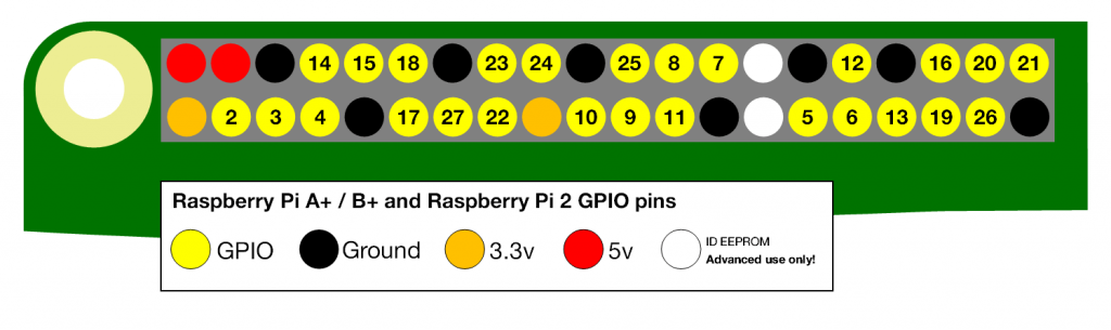
As you can see in the picture above, Pin 3.3V and pin 5V are in a parallel position. Please be careful not to contact pins 5v and 3.3v, because it will damage your Raspberry Pi.
Additional Pin Functions
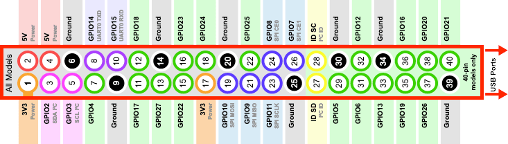
If you have ever used an Arduino board, you must have known digital pins and analog pins. Also, some digital pins have a PWM (Pulse Width Modulation) function. On the Raspberry Pi, all GPIO can be used as a software PWM, and some pins support PWM hardware. Analog sensors can use the PWM function. Here are some special Raspberry Pi pins.
| PWM (Pulse Width Modulation) |
- PWM software is available on all Pins - PWM Hardware is available on GPIO12, GPIO13, GPIO18, GPIO19 |
| SPI (Serial Peripheral Interface) | - SPI0: MOSI (GPIO10); MISO (GPIO9); SCLK (GPIO11); CE0 (GPIO8), CE1 (GPIO7) - SPI1: MOSI (GPIO20); MISO (GPIO19); SCLK (GPIO21); CE0 (GPIO18); CE1 (GPIO17); CE2 (GPIO16) |
| I2C (Inter Integrated Circuit) |
- Data: (GPIO2); Clock (GPIO3) - EEPROM Data: (GPIO0); EEPROM Clock (GPIO1) |
| Serial | TX (GPIO14); RX (GPIO15) |
GPIO BCM and GPIO Board
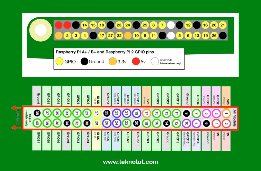
On the Raspberry Pi, Pin can be defined in two ways, using the GPIO Board and GPIO BCM methods.
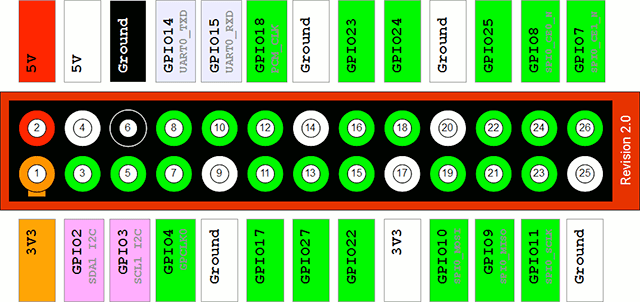
GPIO BCM refers to the default pin of the Broadcom SOC channel chip. In the picture above, GPIO BCM is written in a box outside the red line. For example, if we define pin 17, eating the program will run on GPIO17.
Whereas GPIO Board refers to the naming on the Raspberry Pi board. In the picture above, it is written in a green circle in the red box. GPIO Board is easier to define pins because we only have to count the number of pins. For example, if the GPIO BCM, we define Pin 17 to run GPIO17. On the GPIO Board, we define the pin with pin 11.
We will more easily understand about the GPIO Board and the GPIO BCM after we make the program blink later.
Pinout
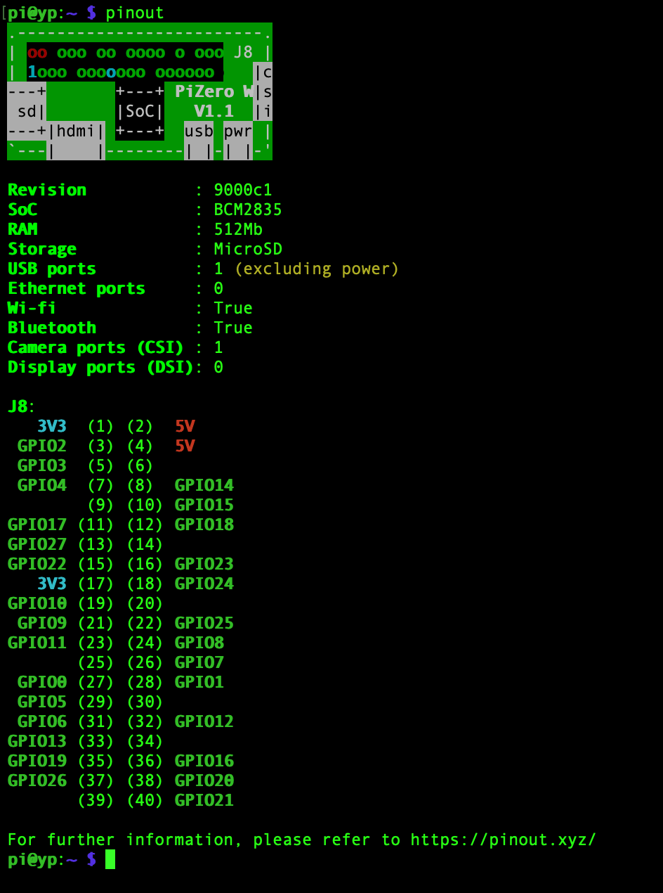
If you doubt your Pin Raspberry Pi mapping, you can see the pin scheme directly by using the command;
pinoutType the command above after SSH login or through the terminal on your Raspberry Pi. An example of the output for Raspberry Pi Zero is as shown below.
OK, after getting to know the pin on the Raspberry Pi, then let's make our first project, the blink project. When installing the jumper cable to the Raspberry Pi or breadboard pin header, it is recommended that the Raspberry Pi be power off to avoid short pins.
Preparation
Here are some tools that must be prepared.
- 1 Raspberry Pi any models (Buy Here)
- 1 Breadboard (Buy Here)
- 2 jumper cable Male to Female (Buy Here)
- 1 220 Ohm Resistor (Buy Here)
- 1 Led 5mm or 3mm (Buy Here)
After finishing, please assemble it in your breadboard with the scheme as shown below.
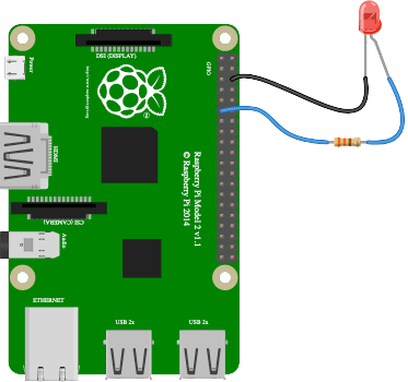
- GND or Led negative on Raspberry Pi Pin 6
- Positive to Raspberry Pi pin 11
On Raspberry Pi, the GPIO command already includes the Raspbian operating system. So we can program GPIO with various programming languages such as Python, Java, C, PHP, bash or can directly use commands. Raspberry Pi GPIO can also be programmed with Scratch programming, which is a visual programming language to learn programming easily.
GPIO Command
With the gpio command, we will easily control the pins, both input and output. For how to use the gpio command, type the following code.
man gpioTo turn on the LED, we need to provide High signal on the pin we choose, while to turn off the LED we will give a Low signal. Try typing the following command.
gpio -g mode 17 out
gpio -g write 17 1
In the command above, your LED should have turned on. In the first line "gpio -g mode 17 out", the -g option is the option to define the GPIO BCM pin as explained earlier, in this case we designate GPIO17 on pin 11 to run the Output mode.
In the second line "gpio -g write 17 1", we write the signal on GPIO17 to be High so that the LED lights up.
To define a pin on a GPIO Board, you can use option -1, for example as follows.
gpio -1 write 11 0With the above command, your LED should turn off. Because we write pin 11 (or GPIO17 on BCM) low. We only need to define mode one time. Once we define mode, then the mode will remain the same until we change it back, or until your Raspberry Pi is restarted.
The gpio command is equipped with the blink option. We just type one command to make the LED on and off. Press CTRL+C to stop the command.
gpio -1 blink 11 In the above command, we command pin 11 (BCM) for a blink, turn on 1 second, turn off 1 second, and so on as long as we haven't pressed CTRL+C.
Bash Script
Well, because Raspbian provides the gpio command, we can program using the basic Linux programming language, Bash. Bash script is a simple script that can help run Linux commands. Bash script like a Batch file if on a Windows Operating System.
Before continuing, we need to know the path of the gpio command, so that we are not wrong. The method is using the which command.
which gpioThe output I get for the gpio command is in the /usr/bin/gpio path. Now let's make the bash script. The first step is to create a file such as blink.sh with the nano command.
nano blink.shThen fill in the following script:
#!/bin/bash

while :
do
        /usr/bin/gpio -1 toggle 11
        sleep 1
done
Press CTRL+X followed by confirmation by pressing the Y button. After that, make the script writable with the chmod command.
chmod +x blink.shThen run the program with the bash command.
bash blink.shor,
./blink.shYour LED should have blinked. The above program will run an infinite loop or endless loop by running the gpio command with the toggle option on the GPIO Board pin 11. The toggle option is an option to write the opposite condition. So if the pin is Low, it will be written High, and vice versa. On the line with the sleep 1 program, it will delay for 1 second before the program continues.
Python
Python is the primary programming language of the Raspberry Pi. If you follow How to Install Raspberry Pi in the previous article. Raspberry Pi has prepared Python 2 and Python 3 by default. So you don't need to install it again.
Python is very rich in libraries, in this experiment, we will try to use a different library, the library RPi.GPIO and gpiozero.
RPi.GPIO Library
To make a project blink with the RPi.GPIO library, we need an additional module, namely time. Create a file with the extension .py with the nano command, for example, I will create a blinkrpi.py file.
nano blinkrpi.pyEnter the following code:
import RPi.GPIO as GPIO
from time import sleep

GPIO.setwarnings(False)
GPIO.setmode(GPIO.BOARD)
GPIO.setup(11, GPIO.OUT, initial=GPIO.LOW)

while True:
     GPIO.output(11, GPIO.HIGH)
     sleep(1)
     GPIO.output(11, GPIO.LOW)
     sleep(1)
Save the file by pressing CTRL+X followed by pressing the Y button. Run the program with the command below. To stop the program press CTRL+C.
python blinkrpi.pyIf there are no errors, your LED will start flashing. The above program will run an infinite loop to write pin 11 (GPIO Board) to high, stop for 1 second, then write pin 11 to be low and stop 1 second.
To better understand, please try changing the board mode to BCM. With the BCM pin written it will be 17.
gpiozero Library
Gpiozero is a library with complete functions. Raspberry highly recommends using this library. The documentation about gpizero can be found on the https://gpiozero.readthedocs.io/en/stable/ page. In this library, the default pin will be defined by the BCM method. Unlike the RPi.GPIO library, gpiozero cannot be configured for pin numbering. However, if you are familiar with the GPIO Board, you can write it directly, for example as below.
- led = LED(17) => Default BCM or the same as BCM17.
- led = LED("GPIO17") => Same as BCM17.
- led = LED("BCM17") => Same as above.
- led = LED("BOARD11") = Defines the pin with the number 11 GPIO Board format.
Gpiozero is optimized for python3, although it can run on python2, it doesn't necessarily work all its functions. In this experiment, we will use python3.
OK, we try to make the project blink with the gpiozero library. Create a file with the extension .py, for example, blinkzero.py with the nano command. Then fill in the following program.
from gpiozero import LED
from time import sleep

led = LED(17)

while True:
    led.on()
    sleep(1)
    led.off()
    sleep(1)
After you have finished saving the program, then run it with the following command.
python3 blinkzero.pyYour LED is already blinking. If you see, gpiozero is easier and simpler. The above program is the same as the previous program that runs an infinite loop with sleep. However, you can program it in another way. The gpiozero library with the LED function has been equipped with a blink function. The above program can be replaced as below, which is shorter and more concise.
from gpiozero import LED
from signal import pause

led = LED(17)
led.blink()
pause()
The above program does not use loops but uses the pause() function of the library signal. This will be the same as an infinite loop, but shorter.
If you want to use the GPIO Board method, you only need to change the line led=LED(17) to led = LED(BOARD17)
It's easier, isn't it?
Conclusion
From the above experiments, we can conclude that managing the GPIO on the Raspberry Pi is not too difficult. Understanding the pin numbering method must be a priority. You have to determine which GPIO Board and GPIO BCM are easy to use in your opinion to be more familiar.
Pin management can use various programming languages. We are not too fixated to use Python. In the next article, we will try to use the PHP programming language to control the LED using a website.
Hopefully, this article is useful.