If you own a Raspberry Pi, you've probably thought about using it for more than just a tiny computer. One of the most popular first projects is a temperature and humidity monitor, whether for a bedroom, a small home server closet, a chicken coop, or a plant shelf.
The go-to sensor for this job is the DHT22. It's affordable, needs only one data pin, and is reasonably accurate. The problem is that many DHT22 tutorials online are outdated: the Adafruit_DHT library that used to be everywhere is no longer developed, and sudo pip install is now rejected by recent versions of Raspberry Pi OS.
The good news is that there's a simpler and more durable way: the driver built into the Linux kernel. There's no library to install, just a single line of configuration, and then temperature and humidity can be read like ordinary files.
In this article, we'll cover everything you need to read a DHT22 sensor with Raspberry Pi and Python, from getting to know the sensor, wiring it on a breadboard, reading data through the kernel driver, and the Adafruit library alternative, to logging data automatically to a CSV file. Let's get started!
What is the DHT22 Sensor?
The DHT22 (also sold as the AM2302) is a digital sensor that measures both temperature and air humidity. Inside it are a capacitive humidity sensor, a thermistor, and a small chip that converts the measurements into a digital signal.
Data is sent over a single data wire using a custom protocol that depends heavily on precise timing. This is why the DHT22 can be a bit fussy on a Raspberry Pi: Linux is not a real-time operating system, so a reading occasionally fails. That's normal, and the fix is simply to read again.
Here's a quick look at the DHT22 specifications according to its datasheet:
| Parameter | DHT22 (AM2302) | DHT11 (for comparison) |
|---|---|---|
| Temperature range | -40 to 80 °C | 0 to 50 °C |
| Temperature accuracy | ±0.5 °C | ±2 °C |
| Humidity range | 0–100% RH | 20–90% RH |
| Humidity accuracy | ±2–5% RH | ±5% RH |
| Supply voltage | 3.3–5.5 V | 3.3–5.5 V |
| Interval between readings | at least 2 seconds | at least 1 second |
You'll find the DHT22 sold in two forms:
- Bare 4-pin sensor: a white body with four legs. It needs an extra pull-up resistor on the data leg.
- 3-pin module: the sensor soldered onto a small board, usually with the pull-up resistor already included. The pins are labeled
+(orVCC),OUT(orDAT), and-(orGND).
This article uses the bare 4-pin sensor. If you have the 3-pin module, the wiring is actually easier because no resistor is needed.
Preparation
Before starting, prepare the following:
- A Raspberry Pi of any model with the 40-pin GPIO header (Pi 3, Pi 4, Pi 5, Zero 2 W, and others).
- Raspberry Pi OS installed and accessible, either with a monitor or over SSH. The commands in this article are intended for Raspberry Pi OS Bookworm (Debian 12) and Trixie (Debian 13). If you haven't set it up yet, follow the guide on how to install Raspberry Pi headless.
- 1 DHT22 sensor (AM2302).
- 1 10kΩ resistor (color bands brown-black-orange-gold). Not needed if you use the 3-pin module.
- A breadboard and 3 female-to-male jumper wires.
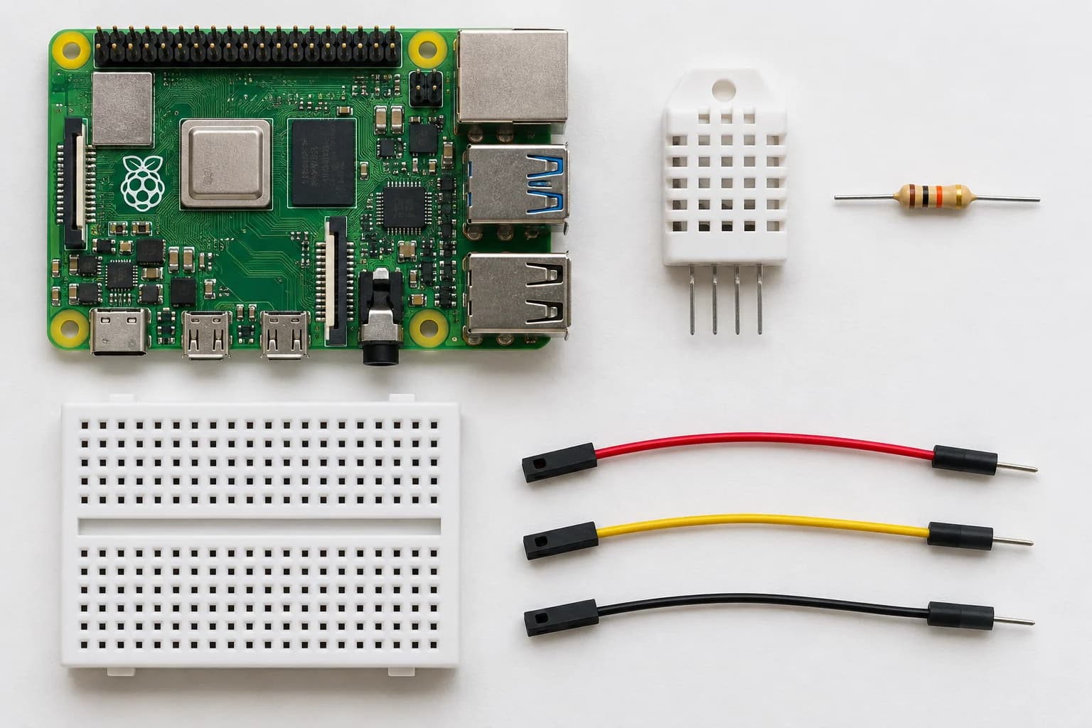 Illustration of the required components: Raspberry Pi, DHT22 sensor, breadboard, 10kΩ resistor, and jumper wires.
If you've never used the GPIO pins before, it's worth trying the first Raspberry Pi Blink project first to get comfortable with pin numbering and the breadboard.
How to Wire the DHT22 to a Raspberry Pi
Step #1: Identify the DHT22 Pins
Hold the sensor with the grille side facing you and the legs pointing down. From left to right, the legs are:
- Pin 1: VCC (power)
- Pin 2: DATA
- Pin 3: not used
- Pin 4: GND
Step #2: Connect the Sensor to the GPIO Pins
Shut down the Raspberry Pi and unplug its power before wiring. Insert the DHT22 into the breadboard, then connect it according to this connection table:
| From | To |
|---|---|
| DHT22 pin 1 (VCC) | Raspberry Pi physical pin 1 (3V3) |
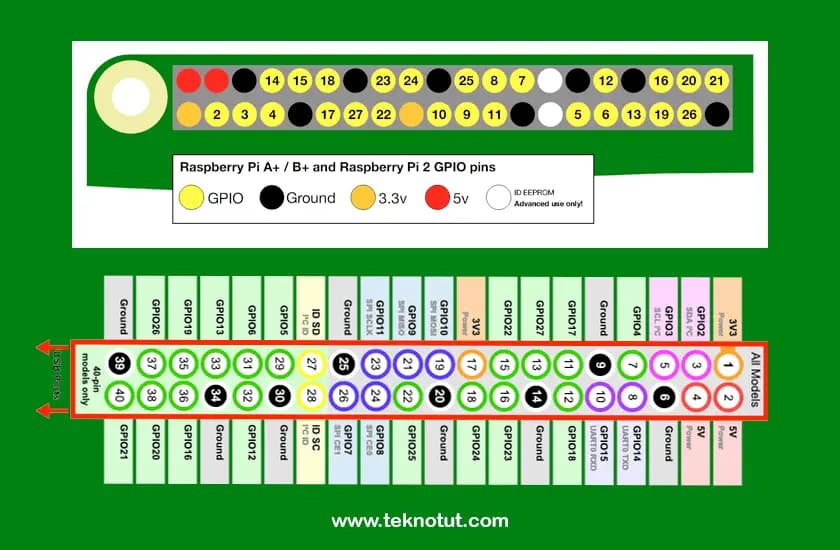
| DHT22 pin 2 (DATA) | Raspberry Pi physical pin 7 (GPIO4) |
| 10kΩ resistor | Between pin 1 (VCC) and pin 2 (DATA) |
| DHT22 pin 3 | Not connected |
| DHT22 pin 4 (GND) | Raspberry Pi physical pin 6 (GND) |
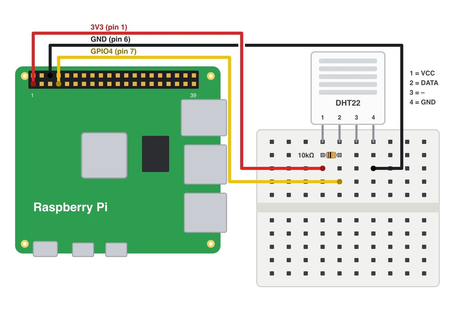 Illustration of the DHT22 circuit on a breadboard. Follow the connection table above.
The 10kΩ resistor acts as a pull-up, keeping the data line at a HIGH level whenever the sensor isn't sending data. The value doesn't have to be exactly 10kΩ: the AM2302 datasheet suggests around 5.1kΩ, and 4.7kΩ resistors are also commonly used.
Voltage warning: Raspberry Pi GPIO pins operate at 3.3V and are not 5V tolerant. That's why we power the sensor from the 3V3 pin, so the data signal coming back to the GPIO is also 3.3V. Never connect the pull-up resistor to the 5V pin.
If you're using the 3-pin module, simply connect + to physical pin 1 (3V3), OUT to physical pin 7 (GPIO4), and - to physical pin 6 (GND), with no extra resistor. The pin order varies between manufacturers, so always read the labels printed on the board.
Once you're sure every wire is in the right place, power the Raspberry Pi back on.
Method #1: Reading the DHT22 with the Kernel Driver (Recommended)
The Linux kernel in Raspberry Pi OS already ships with a driver for the DHT sensor family. We only need to enable it with a device tree overlay called dht11. Don't be fooled by the name: according to the official Raspberry Pi overlay documentation, this overlay covers the DHT11, DHT21, and DHT22 (including the AM230x series).
The advantages of this method:
- No extra libraries: no
pipand no virtual environment. - Timing is handled by the kernel: the sensor signal is read at kernel level, which is more precise than reading it from a Python program.
- No dependency on Python GPIO libraries, which have changed several times across Pi models and operating system versions.
Step #1: Enable the dht11 Overlay
Open the boot configuration file with the following command:
sudo nano /boot/firmware/config.txtAdd this line at the very bottom of the file (below the [all] line):
dtoverlay=dht11,gpiopin=4The gpiopin parameter is the GPIO number (not the physical pin number) connected to the sensor's DATA leg. Its default value is already 4, but we write it explicitly to make it clear. Save the file by pressing Ctrl+X, then Y, and Enter.
Next, restart the Raspberry Pi so the overlay is loaded:
sudo rebootStep #2: Test a Reading from the Terminal
Once the Raspberry Pi is back up, the driver creates an IIO (Industrial I/O) device in the /sys/bus/iio/devices/ folder. Check its contents with the following command:
ls /sys/bus/iio/devices/iio:device0/The output looks roughly like this:
in_humidityrelative_input in_temp_input name of_node power subsystem ueventIf the in_temp_input and in_humidityrelative_input files are there, the driver is active. Now read the temperature and humidity values with the following commands:
cat /sys/bus/iio/devices/iio:device0/in_temp_input
cat /sys/bus/iio/devices/iio:device0/in_humidityrelative_input
The output looks roughly like this:
28400
65300
The values are in thousandths, so 28400 means 28.4 °C and 65300 means 65.3% relative humidity.
Seeing
Connection timed outorInput/output error? Don't panic. As mentioned earlier, DHT22 readings fail once in a while. Wait 2 seconds and run the command again. If it always fails, double-check your wiring (see the troubleshooting section below).
If you have other IIO devices, the number may not be iio:device0. The Python program in the next step finds the folder automatically.
Step #3: Write the Python Program
Create a project folder and the program file with the following commands:
mkdir -p ~/dht22
nano ~/dht22/baca_dht22.py
Then enter the following code:
#!/usr/bin/env python3
"""Read a DHT22 sensor through the kernel driver (IIO)."""
import glob
import time


def cari_sensor():
    """Find the IIO device folder that belongs to the DHT sensor."""
    hasil = glob.glob("/sys/bus/iio/devices/iio:device*/in_humidityrelative_input")
    if not hasil:
        raise SystemExit("Sensor not found. Check dtoverlay in config.txt, then reboot.")
    return hasil[0].rsplit("/", 1)[0]


def baca(folder, percobaan=5):
    """Return (temperature, humidity), or None if every attempt fails."""
    for _ in range(percobaan):
        try:
            with open(f"{folder}/in_temp_input") as f:
                suhu = int(f.read()) / 1000
            with open(f"{folder}/in_humidityrelative_input") as f:
                kelembapan = int(f.read()) / 1000
            return suhu, kelembapan
        except OSError:
            # the reading failed, wait 2 seconds and try again
            time.sleep(2)
    return None


if __name__ == "__main__":
    folder = cari_sensor()
    while True:
        data = baca(folder)
        if data:
            suhu, kelembapan = data
            print(f"Temperature: {suhu:.1f} °C | Humidity: {kelembapan:.1f} %")
        else:
            print("Failed to read the sensor. Check your wiring.")
        time.sleep(5)
A quick explanation of the code:
cari_sensor()looks for the IIO device folder that contains anin_humidityrelative_inputfile, so the program still works even if the device number isn't0.baca()reads both files and divides the values by 1000. If the kernel reports a failure (which Python receives as anOSError), the function waits 2 seconds and tries again, up to 5 times.- The main part of the program prints the result every 5 seconds. Remember, the DHT22 should be read no faster than once every 2 seconds.
Step #4: Run the Program
Run the program with the following command:
python3 ~/dht22/baca_dht22.pyThe output looks roughly like this:
Temperature: 28.4 °C | Humidity: 65.3 %
Temperature: 28.4 °C | Humidity: 65.1 %
Temperature: 28.5 °C | Humidity: 64.9 %
Try breathing gently onto the sensor, and the humidity value will rise right away. Done! Press Ctrl+C to stop the program.
Method #2: Reading the DHT22 with the Adafruit CircuitPython Library
The alternative is the adafruit-circuitpython-dht library, the official successor to the discontinued Adafruit_DHT. This method makes sense if you already use the Adafruit Blinka ecosystem for other sensors. At the time of writing, the latest version is 4.0.12.
Important: if you enabled the overlay in Method #1, remove the
dtoverlay=dht11,gpiopin=4line from/boot/firmware/config.txtfirst and reboot. While the overlay is active, GPIO4 is held by the kernel and can't be used by another library.
Step #1: Create a Virtual Environment and Install the Library
Since Raspberry Pi OS Bookworm, pip is no longer allowed to install packages into the system Python, so a virtual environment is required. Install the dependencies first, following the official Adafruit guide:
sudo apt update
sudo apt install -y python3-venv libgpiod-dev python3-libgpiod
Create a virtual environment inside the project folder, then activate it:
python3 -m venv ~/dht22/env --system-site-packages
source ~/dht22/env/bin/activate
Once it's active, your terminal prompt starts with (env). Now install the library:
pip3 install --upgrade adafruit-blinka adafruit-circuitpython-dhtFor the Raspberry Pi 5 specifically, the Adafruit guide notes that the RPi.GPIO package that gets installed along the way can cause issues and should be removed from the virtual environment:
pip3 uninstall -y RPi.GPIOStep #2: Write and Run the Program
Create a new file with nano ~/dht22/baca_adafruit.py, then enter the following code (adapted from the library's official example):
import time

import adafruit_dht
import board

# sensor DATA is connected to GPIO4 (physical pin 7)
sensor = adafruit_dht.DHT22(board.D4, use_pulseio=False)

while True:
    try:
        suhu = sensor.temperature
        kelembapan = sensor.humidity
        print(f"Temperature: {suhu:.1f} °C | Humidity: {kelembapan:.1f} %")
    except RuntimeError as error:
        # failed reads are normal with DHT sensors, just try again
        print(error.args[0])
    except Exception:
        sensor.exit()
        raise
    time.sleep(2)
The use_pulseio=False option makes the library read the signal directly (bit-banging). According to Adafruit's official example, this may be necessary on Linux single-board computers like the Raspberry Pi.
Run the program (make sure the virtual environment is still active):
python ~/dht22/baca_adafruit.pyThe result is similar to Method #1, with an occasional error message when a reading fails. Keep in mind that the library's own documentation lists a few limitations, including unreliable readings on the Raspberry Pi Zero. If the results are unstable on your device, go back to Method #1.
Comparing the Two Methods
| Method #1: Kernel Driver | Method #2: Adafruit Library | |
|---|---|---|
| Installation | One line in config.txt |
Virtual environment + pip |
| Needs internet | ❌ | ✅ |
| Signal reading | In the kernel | In the Python program |
| Changing the pin | Edit config.txt, then reboot |
Change it in code |
| Best for | Long-term monitoring, simple scripts | Projects already using Blinka |
Logging Sensor Data to a CSV File
Reading the current temperature is fun, but data only becomes truly useful when it's recorded over time. We'll create a small script that writes one line of data each time it runs, then schedule it with cron. This section uses Method #1.
Create a new file with nano ~/dht22/catat_dht22.py, then enter the following code:
#!/usr/bin/env python3
"""Print one CSV line: time,temperature,humidity."""
from datetime import datetime

from baca_dht22 import baca, cari_sensor

data = baca(cari_sensor())
if data:
    waktu = datetime.now().strftime("%Y-%m-%d %H:%M:%S")
    print(f"{waktu},{data[0]:.1f},{data[1]:.1f}")
This script reuses the functions from baca_dht22.py, so both files must be in the same folder. Try running it once with the following command:
python3 ~/dht22/catat_dht22.pyThe output looks roughly like this:
2026-11-14 09:15:02,28.4,65.3Now open your user's cron editor:
crontab -eAdd the following line at the very bottom to log data every 5 minutes. Replace budi with your own username:
*/5 * * * * /usr/bin/python3 /home/budi/dht22/catat_dht22.py >> /home/budi/dht22/data.csvAfter a few minutes, check the result with the following command:
tail -n 3 ~/dht22/data.csvYou can open this data.csv file in a spreadsheet application and turn it into a chart. Pretty cool, right?
Troubleshooting
Here are the most common problems and how to fix them:
| Problem | Likely Cause | Solution |
|---|---|---|
The iio:device0 folder doesn't exist |
The overlay isn't loaded | Check the dtoverlay line in /boot/firmware/config.txt, then reboot |
Always Connection timed out |
DATA wire on the wrong pin, or the sensor has no power | Make sure DATA goes to physical pin 7 (GPIO4), VCC to pin 1, GND to pin 6 |
Frequent Input/output error |
No pull-up, wires too long, or a loose breadboard contact | Add a 4.7–10kΩ resistor between VCC and DATA, shorten the wires |
| Values never change | The sensor is read more often than once every 2 seconds | Wait at least 2 seconds between readings |
error: externally-managed-environment on pip install |
pip was run outside the virtual environment |
Activate it first with source ~/dht22/env/bin/activate |
| Method #2 can't access the pin | The dht11 overlay is still active on the same GPIO |
Remove the dtoverlay line, then reboot |
One note on cable length: the AM2302 datasheet states that when the sensor is powered at 3.3V, the cable should be no longer than 1 meter, because the voltage drop can affect the measurements.
Conclusion
From this article, we can conclude that reading a DHT22 sensor with a Raspberry Pi doesn't require a complicated library. With just three wires, one pull-up resistor, and a single dtoverlay=dht11,gpiopin=4 line in config.txt, temperature and humidity can be read from files in the /sys/bus/iio/devices/ folder.
If you're more comfortable in the Adafruit ecosystem, the adafruit-circuitpython-dht library still works inside a virtual environment. Whichever method you choose, the key is the same: the DHT22 occasionally fails to read, so your program must be ready to retry.
Things to Remember
- Power the sensor from the 3V3 pin, because Raspberry Pi GPIO is not 5V tolerant.
- The bare 4-pin sensor needs a pull-up resistor between VCC and DATA. The 3-pin module usually doesn't.
- Read the sensor no faster than once every 2 seconds.
- Don't use the kernel overlay and the Adafruit library on the same pin at the same time.
Next Steps
Once the data is neatly logged in a CSV file, you can take it further: display a chart on a web page, send a notification when the temperature gets too high, or push the data to an IoT dashboard. If you want a sensor that can sit far from the Raspberry Pi and connect over WiFi, read how to program the ESP32 with Arduino IDE as well.
Resources and Useful Links
- Official Raspberry Pi overlay list (see the dht11 entry)
- Adafruit CircuitPython DHT repository
- Adafruit guide: Installing Blinka on Raspberry Pi
- DHT22 datasheet (SparkFun)
Have a question or run into trouble following this tutorial? Feel free to ask, and stay tuned to Teknotut for the next Raspberry Pi project!
I hope this article helps.