If you're interested in the world of IoT (Internet of Things), you've probably heard of the ESP32 many times already. This tiny, inexpensive board powers countless smart home projects, from lights you can switch on from your phone, to temperature sensors that push data to a dashboard, to smart doorbells.
The problem is that many beginners get stuck at the very first step. The board is in hand, the USB cable is plugged in, but the ESP32 doesn't show up in Arduino IDE, or the upload fails with a confusing error message. Yet once the setup is right, programming an ESP32 is just as easy as programming a regular Arduino.
The good news is that Arduino IDE officially supports the ESP32 thanks to the Arduino core for ESP32, developed directly by Espressif, the company behind the ESP32 chip. You get to write code in the familiar Arduino style, plus access to the ESP32's built-in WiFi and Bluetooth.
In this article, we'll cover everything you need to program the ESP32 with Arduino IDE, from getting to know the ESP32, installing the ESP32 boards in Arduino IDE, building your first blinking LED project, and connecting the ESP32 to WiFi, to fixing the most common errors. Let's get started!
What is the ESP32?
The ESP32 is a microcontroller made by the Chinese company Espressif Systems, with WiFi and Bluetooth built into a single chip. It's the successor to the popular ESP8266, with a faster processor, more pins, and Bluetooth on top.
The classic ESP32 chip uses a dual-core Xtensa processor running at up to 240 MHz, has around 520 KB of internal RAM, and supports 2.4 GHz WiFi and Bluetooth (both Classic and BLE). For comparison, an Arduino Uno runs at 16 MHz with 2 KB of RAM and no WiFi at all.
We usually don't use the bare ESP32 chip directly, but rather a development board that already includes a USB port, a voltage regulator, and buttons. The most common one is the ESP32 DevKit V1 (often called "ESP32 DOIT DevKit" or "ESP-WROOM-32"), which comes in 30-pin and 38-pin versions.
Note: Espressif now also makes other variants such as the ESP32-S3, ESP32-C3, and ESP32-C6. The installation steps in this article are the same for all of them; only the board selection and pin numbers differ. This article uses the ESP32 DevKit V1 with the classic ESP32 chip.
Why Choose the ESP32?
There are plenty of microcontroller boards on the market. Here are a few reasons why the ESP32 is a favorite for IoT projects:
- Built-in WiFi and Bluetooth: no extra modules needed to connect to the internet or to your phone.
- Affordable: an ESP32 DevKit V1 usually costs about the same as an Arduino Uno clone, while being far more capable.
- High performance: a 240 MHz dual-core processor is enough to run a small web server, process sensor data, and send it to the cloud at the same time.
- Programmable with Arduino IDE: you can use the Arduino syntax and thousands of existing libraries.
- Large community: almost any problem you run into has already been discussed in forums or the official documentation.
Of course, there are some downsides too. To be fair, here's what you should know:
- 3.3 volt logic: ESP32 pins work at 3.3V, not 5V like the Arduino Uno. Many 5V sensors and modules need a level shifter.
- Higher power consumption when WiFi is active, so battery-powered projects need to take advantage of deep sleep mode.
- Some pins have special functions and can't be used freely. We'll cover this in the pinout section.
Here's a quick comparison between the ESP32 and other boards beginners often use:
| Feature | Arduino Uno R3 | ESP8266 (NodeMCU) | ESP32 DevKit V1 |
|---|---|---|---|
| Processor | 16 MHz, single-core | 80/160 MHz, single-core | up to 240 MHz, dual-core |
| WiFi | ❌ | ✅ 2.4 GHz | ✅ 2.4 GHz |
| Bluetooth | ❌ | ❌ | ✅ Classic + BLE |
| Logic voltage | 5V | 3.3V | 3.3V |
| ADC pins | 6 | 1 | up to 18 |
| Programmable via Arduino IDE | ✅ | ✅ | ✅ |
Preparation
Before we start, prepare the following hardware and software:
- ESP32 DevKit V1 (30 or 38 pins).
- A micro USB cable that supports data, not a charge-only cable. This is the most common cause of failure!
- A computer running Windows 10/11, macOS, or Linux (for example Ubuntu 24.04 LTS).
- Arduino IDE 2. At the time of writing, the latest version is 2.3.x, available for free on the official Arduino website.
- For the LED project: 1 LED 5 mm (any color), 1 resistor of 220Ω (or 330Ω), a breadboard, and 2 jumper wires (female-to-male if the ESP32 isn't plugged into the breadboard, as in the circuit illustration below).
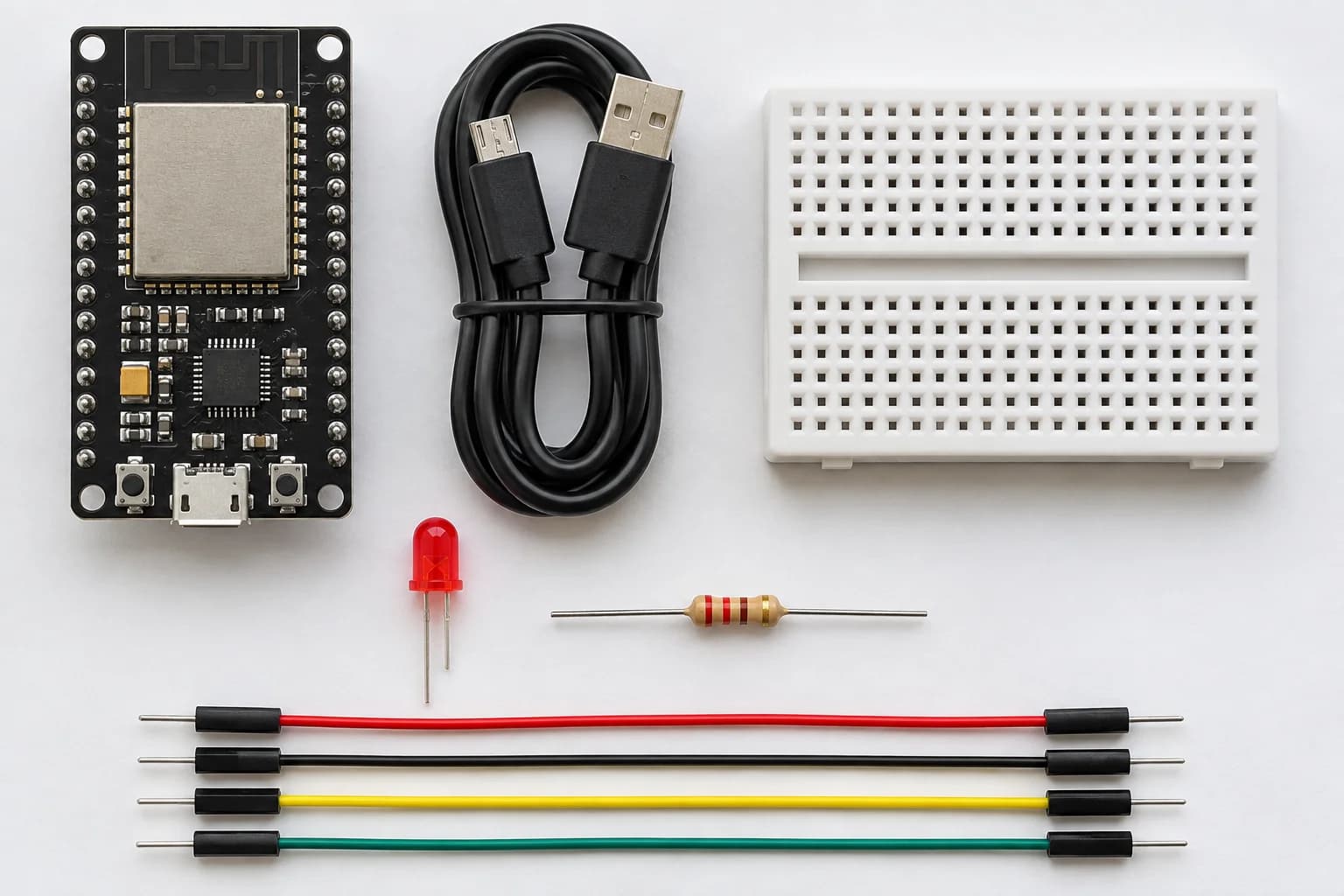 Illustration of the required components: ESP32 DevKit V1, micro USB cable, breadboard, LED, 220Ω resistor, and jumper wires.
If you've followed the tutorial on building your first Raspberry Pi Blink project, the components are almost exactly the same. The difference is that this time, the "brain" is an ESP32.
Understanding the ESP32 DevKit V1 Pinout
Before wiring anything, there are a few important rules about ESP32 pins you should know:
- The pin numbers used in code are GPIO numbers, usually printed on the board with a
DorGprefix (for example,D23orG23means GPIO 23). - GPIO 6 through 11 are connected to the internal flash memory. Never use them, as they can make the ESP32 crash.
- GPIO 34, 35, 36, and 39 are input-only (for example, to read sensors) and can't drive an LED.
- GPIO 0, 2, 12, and 15 are strapping pins that affect the boot mode. Beginners are better off avoiding them for now.
- On many DevKit V1 boards, GPIO 2 is connected to the built-in blue LED.
Voltage warning: all ESP32 GPIO pins work at 3.3V and are not 5V tolerant. Never connect a 5V output from a sensor or module directly to a GPIO pin, as it can permanently damage the ESP32.
How to Install the ESP32 Boards in Arduino IDE
OK, now let's get to the main part. The steps below are intended for Arduino IDE 2.3.x and Arduino core for ESP32 version 3.3.x (the latest version at the time of writing).
Step #1: Install Arduino IDE
Download Arduino IDE from the Arduino Software page, then install it for your operating system:
- Windows: run the
.exeor.msiinstaller and follow the prompts. - macOS: open the
.dmgfile, then drag Arduino IDE into the Applications folder. - Linux: download the AppImage version, make it executable, then run it.
On Linux, make the AppImage executable with the following commands (adjust the file name to match the version you downloaded):
chmod +x ~/Downloads/arduino-ide_2.3.10_Linux_64bit.AppImage
~/Downloads/arduino-ide_2.3.10_Linux_64bit.AppImage
Step #2: Add the ESP32 Board Manager URL
Out of the box, Arduino IDE doesn't know about ESP32 boards. We need to add the official package URL from Espressif.
- Open File → Preferences (Windows/Linux) or Arduino IDE → Settings (macOS).
- Find the Additional boards manager URLs field.
- Paste the following URL, then click OK.
https://espressif.github.io/arduino-esp32/package_esp32_index.jsonIf the field already contains another URL (for example, for the ESP8266), separate each URL with a comma, or click the icon on the right of the field to add it on a new line.
Step #3: Install the esp32 by Espressif Systems Package
- Open the Boards Manager by clicking the board icon in the left sidebar, or via Tools → Board → Boards Manager….
- Type
esp32in the search box. - Select the esp32 by Espressif Systems package, then click Install.
Pick the right package: there's also a package called Arduino ESP32 Boards made by Arduino, which is only meant for official Arduino boards like the Arduino Nano ESP32. For the ESP32 DevKit V1, make sure you install esp32 by Espressif Systems.
The download is fairly large (a few hundred MB) because the package includes the compiler and tools for every ESP32 variant, so give it a few minutes to finish.
Step #4: Connect the ESP32 and Select the Port
Plug the ESP32 into your computer with the micro USB cable. DevKit V1 boards use either a CP2102 (from Silicon Labs) or a CH340 (from WCH) USB-to-serial chip. You can tell which one your board has by reading the small chip near the USB port.
- Windows: if the ESP32 isn't detected, install the CP210x driver from Silicon Labs or the CH340 driver from WCH's official website, depending on your board. The port will appear as
COM3,COM4, and so on. - macOS: recent macOS versions usually recognize both chips out of the box. The port shows up with a name like
/dev/cu.usbserial-0001or/dev/cu.wchusbserial…. - Linux: the drivers are already in the kernel. The port appears as
/dev/ttyUSB0.
On Linux, to make sure the ESP32 has been detected, run the following command right after plugging in the board:
sudo dmesg | tail -n 5The output should look roughly like this:
usb 1-2: new full-speed USB device number 7 using xhci_hcd
cp210x 1-2:1.0: cp210x converter detected
usb 1-2: cp210x converter now attached to ttyUSB0
If you see the line attached to ttyUSB0, the ESP32 has been recognized. Next, add your user to the dialout group so Arduino IDE can access the serial port without sudo:
sudo usermod -aG dialout $USERLog out and log back in (or restart your computer) for the group change to take effect.
Then go back to Arduino IDE and configure the following:
- Select the board via Tools → Board → esp32 → ESP32 Dev Module.
- Select the port via Tools → Port, then click your ESP32's port (for example
COM4or/dev/ttyUSB0).
Leave the other settings in the Tools menu, such as Upload Speed and Flash Frequency, at their defaults.
Project #1: Blinking an LED with the ESP32
The "Blink" project is the "Hello World" of the microcontroller world. We'll turn an LED on and off every second.
Step #1: Wire the LED to the ESP32
We'll use GPIO 23, because it's safe to use as an output and sits at the end of the pin row, making it easy to reach. Wire the components according to the following connection table:
| From | To |
|---|---|
| ESP32 pin D23 (GPIO 23) | One leg of the 220Ω resistor |
| The other resistor leg | The long leg of the LED (anode, +) |
| The short leg of the LED (cathode, −) | ESP32 GND pin |
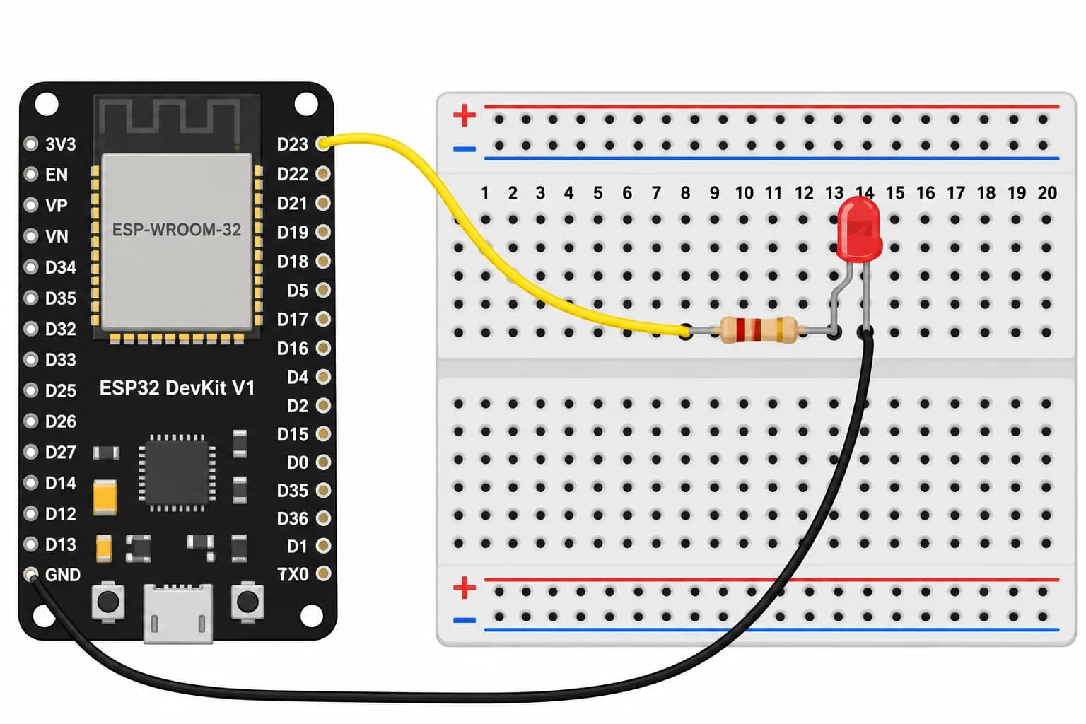 Illustration of the LED circuit on a breadboard. Follow the connection table above.
Breadboard tip: the ESP32 DevKit V1 is quite wide, so if you plug it into the middle of a small breadboard, only one row of holes remains on each side. Use a full-size breadboard, or put the ESP32 on one breadboard and the LED on a second one.
The resistor limits the current so the LED and the GPIO pin don't get damaged. With 3.3V and a 220Ω resistor, only around 5–6 mA flows, which is perfectly safe for an ESP32 pin.
Step #2: Write the Blink Sketch
Create a new sketch via File → New Sketch, then replace its entire contents with the following code:
// GPIO pin the LED is connected to
const int LED_PIN = 23;

void setup() {
  Serial.begin(115200);       // enable the Serial Monitor
  pinMode(LED_PIN, OUTPUT);   // set the LED pin as an output
  Serial.println("ESP32 ready!");
}

void loop() {
  digitalWrite(LED_PIN, HIGH);  // turn the LED on
  Serial.println("LED on");
  delay(1000);                  // wait 1 second

  digitalWrite(LED_PIN, LOW);   // turn the LED off
  Serial.println("LED off");
  delay(1000);
}
A quick explanation of the code:
setup()runs once when the ESP32 powers up. Here we start serial communication at 115200 baud and set GPIO 23 as an output.loop()runs over and over forever. The LED turns on, waits 1 second, turns off, then waits another second.
If you don't have an LED and resistor yet, change
LED_PINto2to blink the built-in blue LED on the DevKit V1 (on boards where the LED is wired to GPIO 2).
Step #3: Upload the Sketch to the ESP32
Save the sketch with Ctrl+S (Cmd+S on macOS), then click the Upload button (the right arrow icon) in the top-left corner. Arduino IDE will compile the code first. The first compile usually takes a while, so be patient.
In the Output panel, you'll see the upload progress, roughly like this:
Connecting....
Chip is ESP32-D0WD-V3 (revision v3.1)
Features: WiFi, BT, Dual Core, 240MHz, VRef calibration in efuse, Coding Scheme None
...
Writing at 0x00010000... (100 %)
Wrote 289280 bytes (159041 compressed) at 0x00010000 in 2.6 seconds
Hash of data verified.

Hard resetting via RTS pin...
When you see Hard resetting via RTS pin..., the sketch has been uploaded successfully and the LED will start blinking. Done!
Upload stuck at
Connecting....? Some DevKit V1 boards can't enter upload mode automatically. Press and hold the BOOT button on the board whenConnecting....appears, then release it once the upload percentage starts moving.
Step #4: Open the Serial Monitor
To see the messages sent by the ESP32, open Tools → Serial Monitor or press Ctrl+Shift+M. Make sure the baud rate in the right corner of the Serial Monitor panel is set to 115200 baud.
The output should look roughly like this:
ESP32 ready!
LED on
LED off
LED on
LED off
If you see random characters instead, the baud rate in the Serial Monitor doesn't match the value in Serial.begin().
Project #2: Connecting the ESP32 to WiFi
Now, this is where the ESP32 really shines compared to a regular Arduino. With just a few lines of code, the ESP32 can join your WiFi network. This project doesn't need any extra wiring.
Step #1: Write the WiFi Connection Sketch
Create a new sketch and enter the following code. Replace YourWiFiName and YourWiFiPassword with your WiFi name and password:
#include <WiFi.h>

const char* ssid     = "YourWiFiName";
const char* password = "YourWiFiPassword";

void setup() {
  Serial.begin(115200);
  delay(1000);

  WiFi.mode(WIFI_STA);          // station mode (WiFi client)
  WiFi.begin(ssid, password);   // start connecting

  Serial.print("Connecting to WiFi");
  while (WiFi.status() != WL_CONNECTED) {
    delay(500);
    Serial.print(".");
  }

  Serial.println();
  Serial.println("Connected!");
  Serial.print("IP address: ");
  Serial.println(WiFi.localIP());
  Serial.print("Signal strength (RSSI): ");
  Serial.print(WiFi.RSSI());
  Serial.println(" dBm");
}

void loop() {
  // check the connection every 10 seconds
  if (WiFi.status() != WL_CONNECTED) {
    Serial.println("Connection lost, reconnecting...");
    WiFi.reconnect();
  }
  delay(10000);
}
The WiFi.h library is already included in the esp32 package we installed earlier, so there's no need to install any additional libraries.
Step #2: Upload and Check the Result
Upload the sketch just like in the previous project, then open the Serial Monitor at 115200 baud. Press the EN (reset) button on the board if the messages don't appear yet. The output should look roughly like this:
Connecting to WiFi.....
Connected!
IP address: 192.168.1.37
Signal strength (RSSI): -58 dBm
If an IP address shows up, your ESP32 is connected to your local network. The RSSI value indicates signal strength: the closer to 0, the stronger. Values around -50 to -67 dBm are good, while below -80 dBm the connection usually starts to become unstable.
Important: the classic ESP32 only supports 2.4 GHz WiFi. If your router uses the same network name for 2.4 GHz and 5 GHz (band steering), and the ESP32 keeps printing dots without ever connecting, try giving the 2.4 GHz network its own name in your router settings.
With the ESP32 connected to WiFi, the door to IoT is wide open: you can build a web server on the ESP32, send sensor data to a server, or control devices from your phone.
Troubleshooting Common Errors
Here are the most common problems when programming the ESP32 for the first time, along with their fixes:
| Problem | Likely Cause | Fix |
|---|---|---|
| Port doesn't appear in Tools → Port | Charge-only cable, or driver not installed | Use a USB data cable, install the CP210x/CH340 driver |
Failed to connect to ESP32: Wrong boot mode detected |
Board doesn't enter upload mode automatically | Hold the BOOT button when Connecting.... appears |
Permission denied: '/dev/ttyUSB0' (Linux) |
User isn't in the dialout group |
sudo usermod -aG dialout $USER, then log out and back in |
/dev/ttyUSB0 disappears immediately (Ubuntu) |
The brltty package claims the CH340 chip |
Remove it with sudo apt remove brltty if you don't use a braille display |
| Serial Monitor shows random characters | Baud rate mismatch | Match the value in Serial.begin() (115200) |
| ESP32 keeps rebooting when WiFi starts (brownout) | Not enough power from the USB port | Try another cable/USB port, avoid unpowered USB hubs |
| LED doesn't light up | LED reversed or wrong pin | Long leg to the resistor, short leg to GND, check the GPIO number |
One thing to keep in mind about the brltty issue on Ubuntu: this package is a service for braille display devices. If you actually use one, don't remove it; look for an alternative such as disabling only the udev rule for the CH340 chip.
Conclusion
From this article, we can conclude that programming the ESP32 with Arduino IDE is actually quite easy. The key is the initial setup: adding Espressif's official Board Manager URL, installing the esp32 by Espressif Systems package, selecting the ESP32 Dev Module board, and making sure the serial port is detected using a USB cable that supports data.
After that, you can write code in the usual Arduino style. We've built two first projects: a blinking LED on GPIO 23 and a WiFi connection that prints the ESP32's IP address.
Things to Remember
- ESP32 GPIO pins work at 3.3V and are not 5V tolerant.
- Avoid GPIO 6–11 (flash) and remember that GPIO 34–39 are input-only.
- The classic ESP32 only supports 2.4 GHz WiFi.
- If the upload gets stuck at
Connecting...., hold the BOOT button.
Next Steps
Now that your ESP32 can connect to WiFi, some interesting next steps are building a web server on the ESP32 to control an LED from your browser, reading a temperature and humidity sensor like the DHT22, or sending sensor data with the MQTT protocol. If you're also curious about single board computers, check out Getting to Know the Raspberry Pi to see how it differs from a microcontroller like the ESP32.
Resources and Useful Links
- Arduino core for ESP32 documentation (Espressif)
- arduino-esp32 repository on GitHub
- Download Arduino IDE
- CP210x USB to UART driver from Silicon Labs
Have a question or ran into a problem while following this tutorial? Feel free to ask, and stay tuned to Teknotut for the next ESP32 project!
I hope this article helps.